
9 min read / Updated 2026-08-25
Prepared by the AutoRepairDiagram catalog team
2008 Ford E350 Fuse Box Diagram: No-Crank Power and Relay Checks
A focused no-crank workflow for the 2008 Ford E350 Super Duty using power distribution, starting and charging, ground, shift-interlock, and anti-theft circuit references.
Confirm the symptom before opening the fuse-box diagram
A no-crank condition means the starter does not rotate the engine. A crank-no-start condition means the starter turns the engine but combustion does not begin. The two symptoms use different diagnostic paths, so listen and watch the instrument panel before testing a fuse or relay.
The 2008 E350 Super Duty catalog includes multiple electrical systems and vehicle configurations. Fuse assignments, relay control, engine options, and module involvement can vary, so match the diagram to the exact vehicle and circuit instead of relying on a generic fuse number from another model year.
Prove battery power reaches the protected distribution path
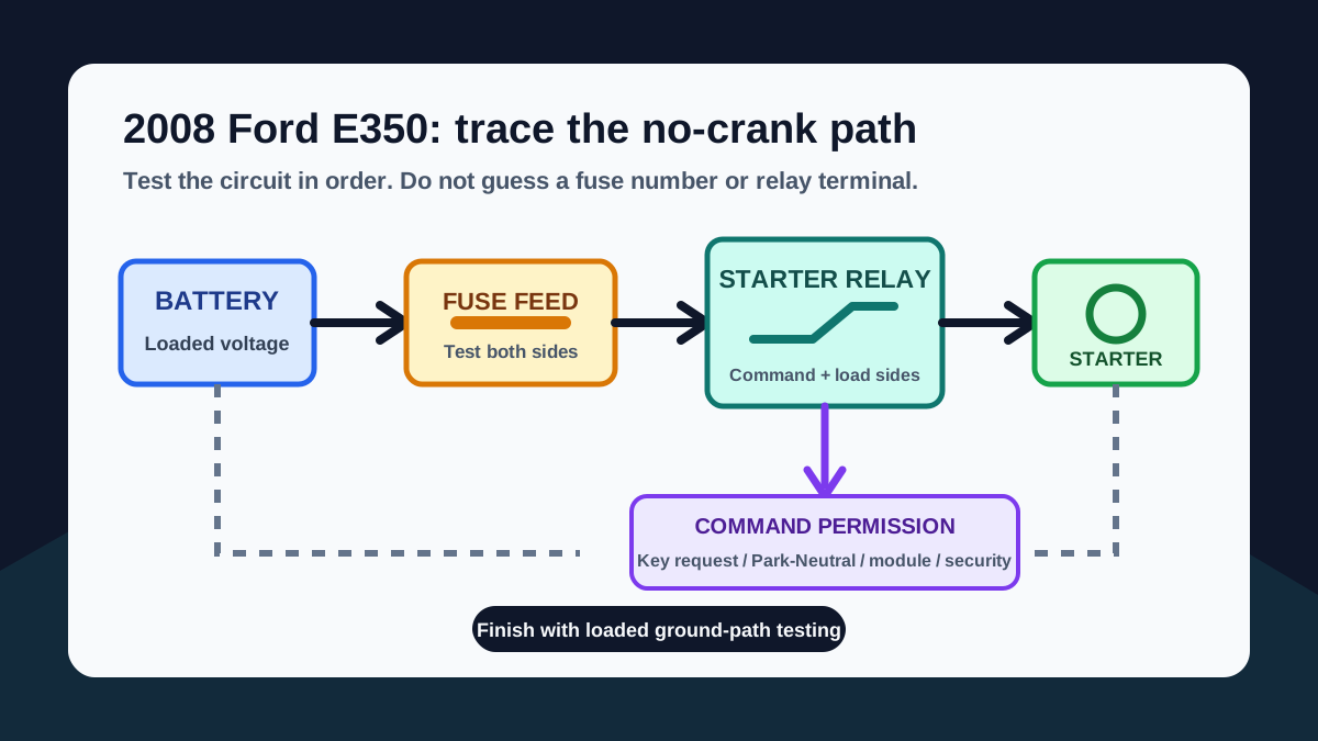
Begin with battery condition, terminal tightness, and visible cable damage. Then use the power distribution diagram to identify the main protected feeds supplying the ignition switch, starter relay, powertrain controller, and starter circuit. Test both sides of the relevant protection device under the same operating condition.
A fuse can look intact and still have a poor terminal connection. A static voltage reading can also appear normal until the starter is requested. Check the circuit while an assistant holds the key in START, following normal workshop safety procedures and keeping the transmission secured in Park or Neutral.
Separate the starter relay load side from the command side
The relay load side carries current toward the starter solenoid. The command side is the lower-current circuit that allows the relay to operate. Depending on vehicle configuration, that command can involve the ignition switch, transmission range or park-neutral input, powertrain control module, anti-theft logic, wiring connectors, and grounds.
A relay click does not prove its contacts are delivering power. No click does not automatically prove the relay is defective. Use the exact connector view or terminal identification from the wiring diagram, verify the feed and output separately, and avoid jumping unidentified terminals because relay layouts are not universal.
Check Park, Neutral, and theft authorization clues
If the starter operates in Neutral but not Park, or changes when the selector is moved, investigate the transmission range or park-neutral input and its adjustment or wiring. Keep the parking brake applied, hold the service brake, and follow safe starting procedures whenever changing selector position during diagnosis.
A flashing or abnormal security indicator can point toward an authorization problem, but it does not replace circuit testing. Compare the Starting/Charging, Shift Interlock, Anti-Theft, and Engine Performance diagrams to understand which module supplies or permits the starter command on the exact configuration.
Use voltage-drop testing while the circuit is loaded
When relay output is present but the starter turns slowly or remains silent, test the positive cable path and ground path while the starter is commanded. Measure across each section of the circuit rather than measuring only battery voltage. Excessive voltage across a cable, connection, relay contact, or ground indicates resistance in that section.
Acceptable limits depend on the circuit and service specification. Record the battery voltage during the attempt, compare both sides of each connection, and follow the manufacturer test limit rather than applying one universal number to every E350 configuration.
Use the result to choose the next diagram
If the relay command is missing, continue through the ignition, park-neutral, module, anti-theft, and ground references. If command and relay output are present, continue through the starter feed, solenoid connection, engine ground, and starter itself. If the engine cranks normally, stop using the no-crank path and move to Engine Performance diagnosis for spark, injection, crank signal, and module power checks.
This sequence prevents unrelated parts from being replaced and keeps each test tied to a known point on the diagram. Label readings as you work so the next step is based on evidence rather than a new guess.
Safety limits for starter and fuse-box testing
Starter circuits can carry very high current. Remove jewelry, keep tools clear of rotating components, use properly rated test equipment, and never bypass transmission safety controls. Do not replace a fuse with a higher rating or repeatedly energize a circuit that is overheating.
This guide explains a diagnostic sequence, not a substitute for vehicle-specific service information. When terminal identification, module authorization, or safe access is uncertain, stop and confirm the exact wiring diagram and service procedure before continuing.
Questions buyers ask
Why does my 2008 Ford E350 start in Neutral but not Park?
That pattern can indicate a transmission range or park-neutral input problem, adjustment issue, connector fault, or wiring problem. Confirm the exact circuit and safe test procedure before replacing a switch or module.
Does a clicking starter relay prove the fuse box is working?
No. A click shows that part of the command side may be operating, but the relay contacts, protected power feed, output wire, starter connection, and ground path still need testing under load.
Can I use a fuse number from another E350 model year?
Do not assume it is the same. Fuse assignments and control strategies can change with model year, engine, body configuration, and production options. Match the diagram to the exact 2008 E350 Super Duty configuration.